Bargraph Meter
Bargraph Meter / Meter Relay
MODEL 1951, 1953, 1954
- ■3 types of light emission of bar graph available:
Orange, Green, Red - ■Clear indicator and alarm display
- ■Power supply available in AC as well as DC
- ■Low cost and easy operation
Model Designation
| 195 | □ | - | □ | - | □ |
| A | B | C |
| Code | Settings |
|---|---|
| 1 | Without setting |
| 3 | 2 set points |
| 4 | 4 set points |
| Code | Input |
|---|---|
| 1 | DC 0-1 mA |
| 2 | DC 4-20 mA |
| 3 | DC 0-1 V |
| 4 | DC 1-5 V |
| 5 | DC 0-5 V |
| 0 | Other than those above *1 |
- *1:
- Input Voltage less than DC 10 V
Input Current less than DC 50 mA
| Code | Power Voltage |
|---|---|
| A | AC 85-264 V |
| 7 | DC 5 V *2 |
| 9 | DC 24 V |
- *2:
- Terminals between power supply and input are non-isolated.
Specifications
| 1951 | 1953 | 1954 | ||||||||||||||
|---|---|---|---|---|---|---|---|---|---|---|---|---|---|---|---|---|
Bar Graph Display |
Display colors | Red, Green, Orange(3 colors Display) | ||||||||||||||
| Display elements | Red & Green | |||||||||||||||
| Bar dots | 101 | |||||||||||||||
| Scale length | 100 mm (1.5 mm width) | |||||||||||||||
| Accuracy | ±(1% of FS + 1 digit) | |||||||||||||||
| Response time | 0.5s | |||||||||||||||
| Scale plate | Black Aluminum(White scale & white characters) | |||||||||||||||
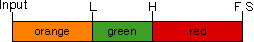
| Setting range | No Relay Output | H :(set value of L + 1%)to 100% L :(set value of H - 1%)to 0%; |
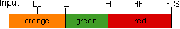
HH :(set value of H + 1%)to 100% H :(set value of HH - 1%)to(set value of L + 1%) L :(set value of H - 1%)to(set value of LL + 1%) LL :(set value of L - 1%)to 0% |
|||||||||||||
| Relay output | H : 1 transfer L : 1 transfer |
H / L : Each contact 1a HH / LL : 1 transfer * |
||||||||||||||
| Hysteresis | 1% of FS | |||||||||||||||
| Contact capacity | AC 125 V, 0.5 A (resistance load) | |||||||||||||||
| Insulation resistance | Between all terminals to outer case DC 500 V, More than 10 MΩ | |||||||||||||||
| Withstanding voltage |
|
|||||||||||||||
| Power supply | AC 85-264 V 50/60 Hz DC 24 V ± 15% DC 5 V ± 5% |
|||||||||||||||
| Power consumption | 7 VA(AC 85-264 V) 6 W(DC 24 V) 3 W(DC 5 V) |
|||||||||||||||
| Operating temperature | 0 to 45°C | |||||||||||||||
| Storage temperature | -20 to 70°C | |||||||||||||||
| Weight | Applox. 400 g | Applox. 420 g | ||||||||||||||
*HH and H:Common terminals are common, LL and L:Common terminals are common
Input Specifications
| Code | Input Signal | Input Impedance |
|---|---|---|
| 1 | DC 0-1 mA | 200 Ω |
| 2 | DC 4-20 mA | 10 Ω |
| 3 | DC 0-1 V | 1 MΩ |
| 4 | DC 1-5 V | |
| 5 | DC 0-5 V |
Colors of Bar Display
●1951・1953
●1954
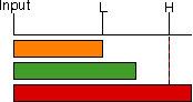
●Option Display
| No. | 1 | 2 | 3 | 4 | 5 | 6 | 7 | 8 | 9 | 10 | 11 | 12 |
|---|---|---|---|---|---|---|---|---|---|---|---|---|
| Max. value | 1 | 1.2 | 1.5 | 2 | 2.5 | 3 | 4 | 5 | 6 | 7.5 | 8 | 9 |
| Division No. | 50 | 24 | 30 | 40 | 50 | 30 | 40 | 50 | 30 | 37.5 | 40 | 45 |